Back Up
Optimizing Low Noise Amplifiers
Magyar    English
Back


How to develop low noise amplifiers

I followed the following concepts to make the preamplifier low-noise:
- Internal noise sources:
Impedance Matching
Circuit technologies
- External noise sources:
Low-noise power supply
Shielding
Ground Loop
Radio-frequency interference (EMI, RFI)


The circuit diagrams illustrated below are only drafts to explain the theoretical operation only and probably needs additional components to work in practice.


• Impedance Matching

Let's see some basic concepts first:

Thermal Noise and Noise Figure

Detailed Wiki Page of Thermal Noise and Noise Figure.

The Thermal Noise is a random voltage (or current) generated by all electric resistances, in the function of temperature. In the audio world it is rarely mentioned because usually it has low enough level to be ignored - but not for MC head amplifiers, see the detailed computations below. Note that it must be taken into account in the case of transformars too.
The thermal noise can be calculated exactly (see this page). For audio circuits it is recommended to calculate 15-20 kHz bandwidth. For example: a device having 40Ω internal resistance generates cca 0.1 µV (microvolt) effective noise voltage. The "device" can be anything (microphone, pick-up cartridge, transformator, cable, etc...), if it has resistance. The amplifier can only make it worse in the further processing, so it determines the theoretical limit of the SNR (Signal to Noise Ratio).
A curiosity of physics that every resistor, independently from its resistance, generates cca 2.6*10-16W noise power in the audio frequency range, at room temperature. The noise voltage and current can be calculated this way too.

The Noise Figure gives the noise degradation between two points of the signal path. It is also not (or at least rarely) used in connection with audio devices (rather in radio engineering), because it is pointless when listening music. However, it can be useful for engineers: it shows how close to the theoretical limits we are. In this case the input comes from e.g. the cartridge (where the noise is determined by the thermal noise), and the signal goes through the amplifier: at the output we have worse signal-to-noise ratio (SNR) than at the input. The ratio between the two SNR values is the Noise Figure.

The Signal to Noise Ratio (SNR)

This is more useful for music listeners: it gives the ratio between peak signal level and the noise. This is what must be optimized, the previous parameters only help this procedure.


In the function of Generator Impedance we must use different circuit technologies:

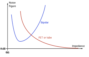
Extremely high impedance needs field-effect device (FET or tube) to reach the lowest noise, because they have very low input current (usually low enough to be ignored), so they produce some orders lower current noise than bipolar transistors. They can approach the 0dB noise figure close enough even though having higher voltage noise (see the chart below).
Average impedance can be good for both field-effect devices and bipolar transistors - lower impedances the more optimal for bipolar transistors, but no strict limit between them. The bipolar transistors have significant current noise, but lower generator impedance the lower importance of current noise.
Low impedance can be optimal for bipolar transistors, due to the voltage noise of the field-effect devices. As a special case, the silicon-germanium transistors can produce even lower noise.

Let's see a generic chart for calculating noise:

The chart shows that the field-effect devices can produce low noise for high impedances - even they have bigger voltage noise, because of the current noise of bipolar transistors. The bipolar transistors can be better in the lowest impedance range, but in the practice there is a significant overlap between them.

Let's see the noise model of bipolar transistors:
Noise model of bipolar transistors
Legend:

Rb': Internal base-connection resistance
Vnb: Thermal noise of Rb'
Inb: Noise component of the base current
Inc: Noise component of the collector current

Noise model of an input stage:
Simplified noise model of a bipolar input stage
Legend:

Vg: Input signal voltage
Rg: Internal generator resistance
Vng: Thermal noise of the generator (due to Rg)
C: Input coupling capacitor
R2, R3: Feedback network
Dashed line means the transistor model above
Red line: the path of Inb (see in the text below)

Note: the DC operating point setup is not shown in the picture.

Let's see the possible noise sources:

1) Vng (generator thermal noise):
This noise is produced by the generator (signal source) itself (see the section thermal noise). There is nothing to do with it, but try to keep the noise of the amplifier at a lower level to reach the possible lowest noise.
Let's see some examples:
Note that it is the noise of the signal source, so it can only be worse at the output of any amplifier (or transformer).

2) Vnb (Thermal Noise of the transistor):
This noise is caused by the resistance of the internal base connection. Because it is usually not mentioned in the documentations, it is hard to find proper types. In general, if it is missing from the doc, that transistor is not suitable for MC head amplifiers. If it is given (called rbb', or Bulk Resistance), then it must be smaller than the generator resistance - or else it would increase the noise. For MAT02 it is 0.5Ω, which is small enough, even for extremely low impedances. Some other suggestions are: 2SD786, 2SB737, MAT12, MAT14, SSM2212

We can also select some preamplifier transistors with extremely high transition frequency because these types usually must have low enough rbb', even if it is missing from their documentation. These can be significantly cheaper and easier to find. However, the high frequency (probably in GHz range) means an important problem: the circuit must be designed as a microwave amplifier - even if it operates only in audio frequency range, or else it will oscillate. I tried BFW16A first and worked for my MC10 cartridge well enough. However, it has low current amplification factor, so probably cannot be used for higher impedances. Later I tried BFP193 and BFU768: these are better (even for higher impedances - e.g. 40Ω), but hard to prevent the oscillation (8GHz and 37GHz FT). At least, if it succeeds, we get low noise and low distortion, superb sound.

Másik kiválasztási szempont lehet, hogy extrém magas határfrekvenciájú, kiszajú előerősítő tranzisztort keresünk - lehet hogy ilyent könnyebb beszerezni, és biztosan olcsóbb is. Az első amit kipróbáltam, az a BFW16A típus volt. Sajnos az adatlapja szűkszavú, de elsőre jó volt. Az áramerősítési tényezője elég alacsony, ezért inkább extrém kicsi impedanciákra jó (pl. Ortofon MC10-hez). Mostanában próbálkoztam BFP193 és BFU768 típusokkal, ezek már egészen kiválóak. Persze, a nagy határfrekvencia átok is egyben: az áramkört mikrohullámú szempontok szerint kell tervezni, hiába csak hangfrekvenciás.

According to my attempts, the MAT02 or SSM2212 are the best. Easy to build (no microwave oscillation), low noise, good quality sound.

To build MM or MI preamplifier, this kind of noise probably can be ignored.

3) Inc (noise of the collector current):
4) Inb (noise of the base current):

• Circuit technologies

I am trying to develop my devices to be immune against external noises (such as 50/60 Hz hum, mobile phone, etc).
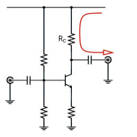
Let's see the schematic of a generic input stage:

The red line shows the way of the noise from the power supply. As you can see, it is passed to the output directly, because the collector resistance is usually smaller than the output impedance of the transistor (or FET or tube) (Zo=1/h22e - see more details at
h-parameter modell).

However it is frequently used - probably due to its simplicity. Usually the power supply is optimized against noise (e.g. using battery), however, the noise can be reduced by using some circuit technologies.
Let's see the example:

On the left side is a small modification: the output is grounded to the power line. Usually it cannot be used this way, but in theory it works. On the right side is a more complicated example which can really work.
The noise from the power line is reduced by Rc/(Rc+Zo). Because Zo is usually higher than Rc significantly, it can produce a high enough suppression of the noise.
Note that the noise coupled by the base ladder also should be suppressed.

Another possibility is using balanced signals. It is common in studio technology and seems to be very useful. Unfortunately, I see it infrequently in audiophile environment.
Let's see this circuit:

The input is unbalance yet (it is not under optimization here), but the output signal is handled in balanced way. The noise from the power line is suppressed by the previously mentioned ratio by both transistors, but in addition, the differential output noise is given by the two suppression difference (which is usually caused by the difference of Zo values of transistors). So, the noise can be even lower in this case - provided that the following stage has good enough CMRR (Common Mode Rejection Ratio).
Also note that there is no noise coupled to the base circuit (see the corresponding comments at the previous circuit).
The Analog Devices has some Matched Transistor Pairs for such purpose.

So far the noise sources were internal (resistors and semiconductors). The noise source can also be external, lets see below:

• Low noise power supply

In addition to the previously mentioned technologies, the noise of the power supply can also be optimized. I do not want to mention any details about it, because it is another big topic.
If you do not want to change an existing amplifier, it can be a trivial method to make some noises lower.
Of course, all of these technologies can be combined for the best result.

• Shielding

The amplifiers can also receive noises from the external field in capacitive or inductive way. The shielding is a simple and efficient way to reduce such noises.
Capacitively coupled noises can be filtered out by a thin conductive foil (e.g. copper foil). It is more important for high impedance points.
Inductively coupled noises can be filtered out by magnetic shields - however, at high frequencies the copper foil also can be enough. For audio frequency circuits some good magnetic conductor shall be used (e.g. permalloy foil). For low signal levels it also can be useful to reduce unnecessary wire loops. Also watch out for inductors, they also can receive such noises (in addition, I would recommend not to use inductors as much as possible).

• Ground Loop

The
Groud Loop is a common and very annoying problem in audio signal handling. Usually it causes 50/60Hz hum, the details are described on the page. However, I must comment the solutions mentioned on that page (and on the net generally), because there are some very "interesting" solutions.
So, the followings are mentioned on the net:

Cut the ground line #1: (wrong solution)
Break in the shield
Simple and cheap solution to break the connection of the shield at the load end. The loop is really prevented, but our problem is not the loop itself but the noise (hum). The noise it not cancelled this way, moreover, it can be even higher because the whole noise voltage of the loop will be added to the signal at the load.
So, it will reduce the loop current only, not the noise.

Cut the ground line #2: serial resistor in the loop (wrong solution)
Break the loop by a serial resistor
Very similar to the previous case (see there). The resistor (being significantly higher than the loop resistance) does reduce the loop current but does not reduce the noise voltage, so we can also expect high level of noise.

Cut the ground line #3: remove the ground in the power cord (dangerous solution)
Remove the ground line in the power cord
The hazardous nature of this "solution" is emphasized on the other web pages too, but it is common enough because it really can reduce the noise (not only the loop current, as the previous solutions do). But it can cause life hazard which does not worth the result. In addition, it is less efficient at higher frequencies, e.g. for switching mode power supplies, where the noise of the switching stage is usually directed through the ground line.
So, this solution is absolutely contraindicated.

I would like to emphasize again that the solutions which break the ground line are theoretically wrong.
Let's see some working solutions:

Additional ground line
Using additional ground wire
There is an additional ground wire, in parallel with the shield. In this case the resistance of the ground wire is reduced, reducing the noise voltage between two sides. However it gives lower noise, this is also a halfway measure because cannot eliminate the problem, but can reduce the noise.

Using Isolation Transformer
Isolation Transformer
The Isolation Transformer gives a really good way to prevent both the current loop and the noise.
However, it can be expensive (especially an audiophile solution). The development of such a transformer is not easy, the impedance matching can also be problematic, especially if the input/output ports were originally not designed to connect to transformer. Without proper match, we can have problems with frequency response and/or distortion.
It is a recommended way to prevent ground loop.

Using balanced signals
Balanced Signal Handling
IMHO, the Balanced Signal handling is the best way to prevent ground loop, because the ground wire is not part of the signal path in this case. That's why I prefer using balanced signals on my devices - I can forget about the ground loop for good. It is simpler, better, and cheaper than using unbalanced wires and applying halfway measures afterwards. The longer cable leans toward balanced signals, the unbalanced cables can be good only for short distances.
It is commonly used in studio technology.
It is also a recommended way to prevent ground loop.


• Radio-frequency Interference

The electronic devices, having nonlinear components, can receive (demodulate) unwanted redio-frequency signals. It is true for all the bipolar, FET, and vacuum-tube devices.
There is a good
description about EMI (ElectroMagnetic Interference), see the details there.

Any broadcasting (mainly the local ones), CB radios, or any device emitting radio-frequency signals can interfere the audio systems. Sometimes it can be surprising to receive such signals from e.g. vacuum-cleaner, coffee grinder, etc. In the worst case an exotic radio station can also be received, but it is a very unlucky case, having e.g. unwanted oscillation on the frequency of the station.
Nowadays, the most important noise source is the mobile phone. Its power is high enough (cca 2W, in pulsed mode), and it can be close enough to our sensitive devices. That's why the prevention is important in the development phase of the audio devices - I would like to show some methods below. The sound sample at right is a mobile phone call near to an audio device.
Noise caused by a mobile phone

A trivial solution can be to filter out the unwanted high-frequency signals at the input. Fortunately, they are out of the audio band, and usually can be filtered by simple circuits.
Let's see some solutions:

Filtering unbalanced signals
Filtering unbalanced input
In the case of an unbalanced input the input signal and the RF noise arrives together, so they can be separated by a low-pass filter. However, this filter design has some limitations by the generator impedance and the amplifier input impedance. For example this is a MM amplifier input, where the input resistance is specified as 47kΩ, and the input capacitance is also must be calculated (see these details on a separated page).

Filtering balanced signals
Filtering balanced input
The balanced signal handling itself can help to solve this problem too - mainly because the audio signal is in differential mode, and the unwanted noise comes in common mode. So, they can be separated by technology, not only by frequency.

Using high-frequency semiconductors

Using such parts is usually contraindicated (due to the ability of oscillation). However, in some special cases (see the details in the MC head apmlifier section), it can be necessary. I try to describe some possibilities to prevent high-frequency problems.