 |
 |
|
 |
|
This is the original motor of the Taya DP510: 16 poles magnet, three phases synchronous motor. It is, or similar motors are, widely used in other direct-drive turntables. What was the problem? These are the most important problems:
|

|
|
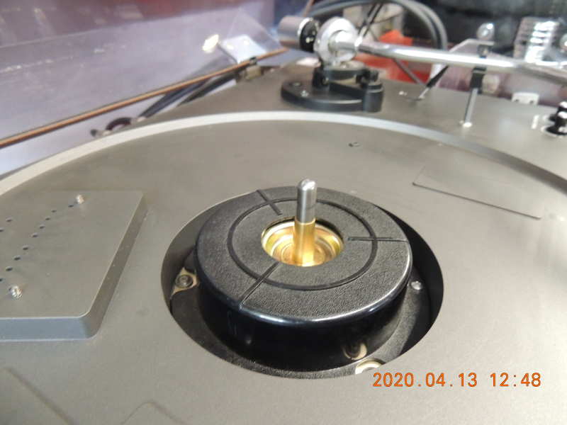
Originally, the motor is bolted down on the plastic cover. As you can see, the arm is also on the same surface, so the vibrations of the motor can be received by the head easily. However, the cover has some bracings, it does not make enough attenuation on the vibrations. |
|
| If the motor is fixed strongly on the hardwood plinth, the mass of the plinth can help to make the operation silent. |

|
|
The original winding. The most important problem is the asymmetry of the electrical parameters (resistance and inductance) of the coils (see this table).
Additional problem is that the wires are not fixed (they can produce mechanical noise). There are iron parts within the gaps: they also can produce noise because they are not fixed
at all and they are in strong magnetic field. You can see 3x2 small coils in the middle: these ones produced the control signals for three phases. Instead of them I use Hall cells (see the details here). |

|
||||||||||||||||||||||||||||||||
|
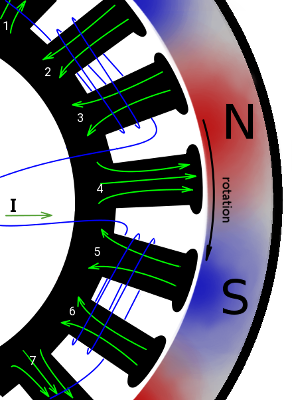
One phase of the original winding, as the previous picture shows. The magnetic field is also shown. The coils are made in an interesting way: they are put on two segments of the iron core. It is probably to simplify the production, the induced magnetic field is exactly the same as it would be winded on one segment, as you can see on the next picture. However, the electrical parameters are slightly worse this way. You can see its solution on the previous picture. Another interesting thing: 3 phases of 16 pole would need 48 segments on the iron core, however, there are only 24 of them. It is also for reducing the noise because the opposite poles of the magnet can eliminate the noise of each other this way. In addition, only half number of coils are necessary. |
|
||||||||||||||||||||||||||||||||
|
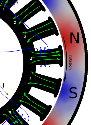
One phase of my new winding. As the picture shows, its magnetic field is exactly the same as the original one. However, its implementation is more difficult, but at least provides more accurate electromagnetic parameters. |
|
||||||||||||||||||||||||||||||||
|
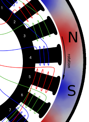
All the three phases of the coil. They can provide rotating magnetic field. Note that the working and feedback coils are the same but using different wire diameters. |
|
||||||||||||||||||||||||||||||||
|
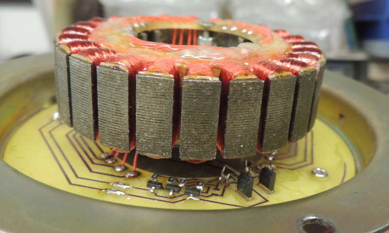
My new winding. The coils are lacquer-impregnated to protect the wires from damage and lower the noise produced by moving wires. Yes, this is a game of endurance to make it by hand. There are Hall cells under the coils. Such a sensor is necessary because the magnet do not induce any voltage in stopped state, and therefore the control circuit cannot find out how to start. But its signals have significantly higher distortion than the voltage induced in the coils, that's why it is used only for starting. However, the motor has three phases, it is enough to have two such sensors (in cca 90 degrees phase shift) because the software can compute the three phase control signals. |
|
||||||||||||||||||||||||||||||||
| The motor has two windings with the same number of turns but with different sized wires: the working coil (thicker wire) and the feedback coil (thinner wire). The table contains the parameters of the working coil (three phases) for the original and for my modified windings. You can see that the original winding has significant differences between three coils while my winding has better symmetry. It is important to keep the operation silent: the result of the three force vectors must form a steady torque. Higher asymmetry produces higher noise. |
|
||||||||||||||||||||||||||||||||
|
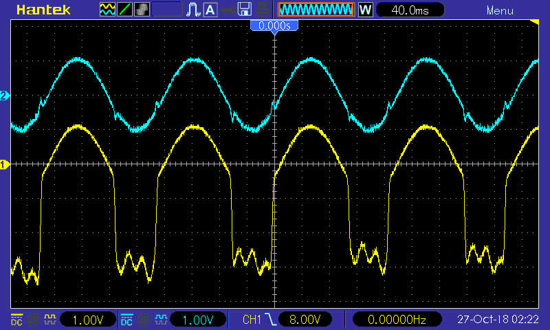
The original signals measured on the coils, at 33 1/3 RPM. The lower signal is the voltage of the driver coil, and the upper one is the feedback coil. This is one of the three phases. The other two are similar, but with 120 degree rotation. The sharp edge on the driver coil is the signal from the driver circuit, and you can also see the hum from the poorly filtered power supply. Such a driver signal induces disturbing noises: the edge of the driving current makes a jump in the torque of the motor, and the power supply hum also makes disturbance. |
|
|
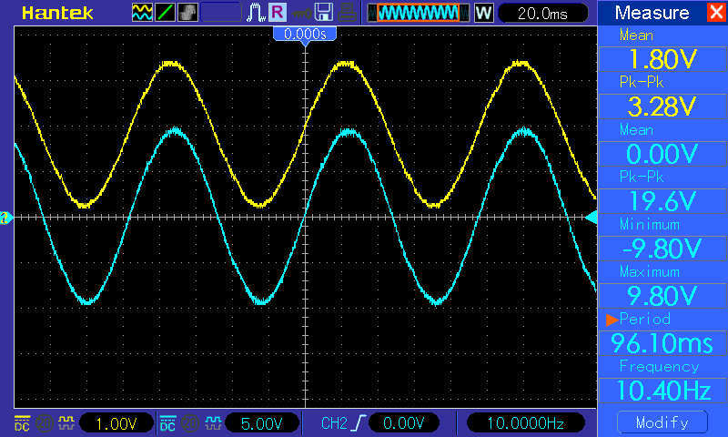
Signals of my driver circuit at 78 RPM. The lower signal is also the voltage of the driver coil, and the upper one is the feedback coil (however, the signal colours are swapped). The sinusoidal driving signal results in a steady torque of the motor, eliminating all other disturbing forces. Of course, it is true only if the mechanical and electronic parts are symmetric. See also the measurement results on the picture - it shows the quality of the driving signals. This measurement was made at 78 RPM speed (the original hardware does not have this option), but other speeds would make similar result. The feedback coil has a 1.8V offset, because it is processed by a A/D converter having 3.6V reference. The MCU processes the driving signals from this input. See the detailed description here. |
|
|
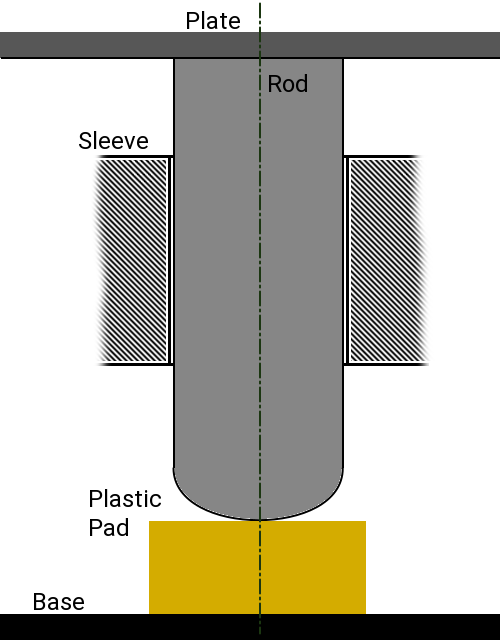
The original bearing. Similar solution is used in most of turntables. I tried some different materials for the pad (different kind of plastics, metal ball, rubber, etc) but none of them was good enough, so I created magnetic levitation bearing, as described on the next pictures. |
|
|
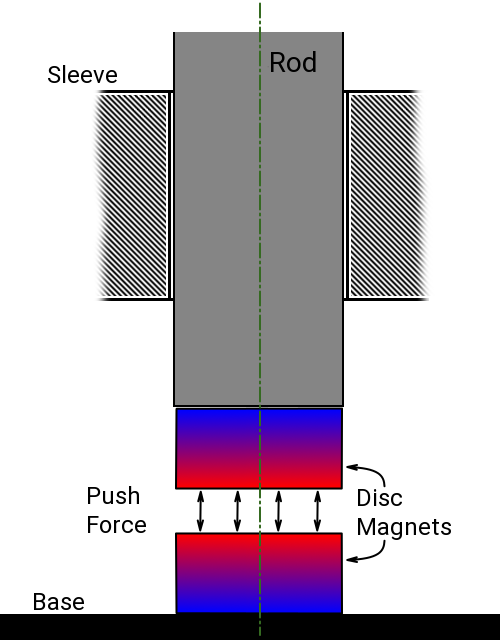
The theory is very simple: same magnetic poles push each other and decreasing distance increases the force. It is ideal for this purpose, as you can see on the picture. However, there is one problem: the force produced by one pair of magnet is not enough. Its diameter is limited by the rod (cannot be bigger than the rod), and increasing its length does not increase the force because it also increases the length of the magnetic field. One possible solution is on the next picture. |
|
|
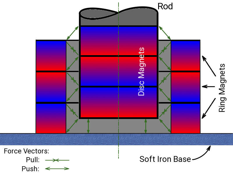
Trivial solution is to multiply the number of magnets - however, the implementation is a little more complicated. It can be done by using disc and ring magnets as you can see on the picture. The magnets are glued - however it is slightly difficult to make it because they push each other. The picture shows the position of the maximum lifting force. The arrows show the forces of each magnet. The size of magnets if the rod diameter is 7mm:
The result is good enough: this part does not produce any noise! |
|
|
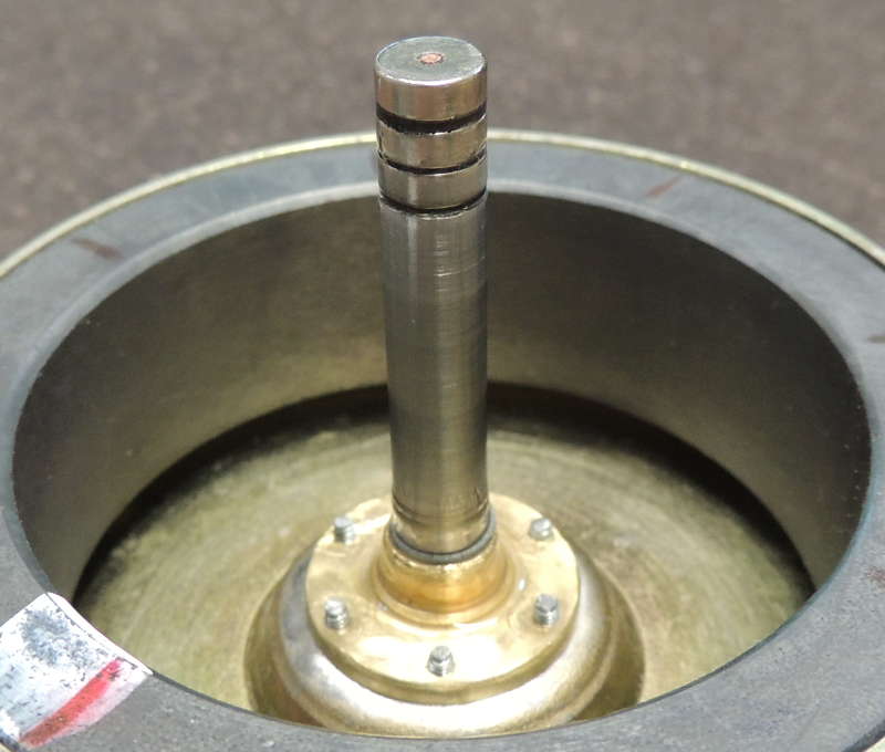
The previous theory is realized in the practice. There is a copper rod (d=1.5mm) glued in the center: it helps in positioning and makes it stronger and more reliable. You can see the centering screws in the middle, as it is described in the section balancing the rotor. |
|
|
This picture shows two positions of the rotor (outer ring magnet) with 180 degrees rorarion. You can see the problem:
significant difference of the air gap. Beacuse the air gap determines the force, the forces of two opposite points do not compensate each other,
resulting in a force perpendicular to the axis which makes the rotating noise higher. The following pictures show the centering procedure. |

|
| Originally, there is a bronze spacer between the rod and the magnet (see the picture). It is fixed with flanging, so I ground it down. |

|
|
Because the spacer fits tightly, its hole must be widened by cca 1mm to have enough space, as you can see the small gap on the picture. I made 6 threaded holes in the spacer (M2 sized), You can see its bottom-view on this picture. The most problematic step is how to fix the magnet in its centered position. To do it, I coiled some turns of thin paper on the iron core to hold the rotor tightly. I put the rotor on, tightened the screws, and that's all. Of course, the papaer must be removed. :-) |

|
|
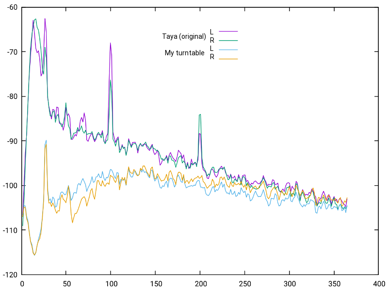
Silent track is recorded from Ortofon Pick Up Test Record 2 with the original Taya device, and with my new hardware. The lower part of the spectrum is displayed here, because the higher frequencies do not show significant information.
The difference is important: the 26 Hz peak is generated by the motor, and the higher range is mostly generated by the bearing. In the lower range the difference is cca 20 dB. The range below 20 Hz has an additional active filter, that is why the difference is bigger here. The 100 and 200 Hz peak is also noticable: these are noises from the power transformer of the Taya. On the new diagram there are no such peaks at all. |
|